Workflow Inputs
Introduction
OpenStudio-ERI requires a building description in an HPXML file format. HPXML is an open data standard for collecting and transferring home energy data. Using HPXML files reduces the complexity and effort for software developers to leverage the EnergyPlus simulation engine.
HPXML Inputs
HPXML is an flexible and extensible format, where nearly all elements in the schema are optional and custom elements can be included. Because of this, a stricter set of requirements for the HPXML file have been developed for purposes of running an Energy Rating Index calculation.
HPXML files submitted to OpenStudio-ERI undergo a two step validation process:
Validation against the HPXML Schema
The HPXML XSD Schema can be found at
hpxml-measures/HPXMLtoOpenStudio/resources/hpxml_schema/HPXML.xsd. XSD Schemas are used to validate what elements/attributes/enumerations are available, data types for elements/attributes, the number/order of children elements, etc.
Validation using Schematron
The Schematron document for the ERI use case can be found at
rulesets/resources/301validator.sch. Schematron is a rule-based validation language, expressed in XML using XPath expressions, for validating the presence or absence of inputs in XML files. As opposed to an XSD Schema, a Schematron document validates constraints and requirements based on conditionals and other logical statements. For example, if an element is specified with a particular value, the applicable enumerations of another element may change.
Important
Usage of both validation approaches (XSD and Schematron) is recommended for developers actively working on creating HPXML files for Energy Rating Index calculations:
Validation against XSD for general correctness and usage of HPXML
Validation against Schematron for understanding XML document requirements specific to running ERI calculations
HPXML Software Info
High-level software inputs are entered in /HPXML/SoftwareInfo.
HPXML Calculations
The OpenStudio-ERI calculation(s) to be performed are entered in /HPXML/SoftwareInfo/extension.
Element
Type
Units
Constraints
Required
Default
Description
ERICalculation/Versionstring
See [1]
No
<none>
Version(s) to perform ERI calculation; multiple allowed
CO2IndexCalculation/Versionstring
See [2]
No
<none>
Version(s) to perform CO2e Index calculation; multiple allowed
IECCERICalculation/Versionstring
See [3]
No
<none>
Version(s) to perform IECC ERI calculation; multiple allowed
EnergyStarCalculation/Versionstring
See [4]
No
<none>
Version(s) to perform ENERGY STAR ERI calculation; multiple allowed
DENHCalculation/Versionstring
See [5]
No
<none>
Version(s) to perform DOE Efficient New Homes ERI calculation; multiple allowed
Warning
For the IECC ERI compliance calculation, OpenStudio-ERI does not perform additional compliance checks beyond calculating the ERI. For example, it does not check the building thermal envelope (2021 IECC, Section R406.3). It is the software tool’s responsibility to perform these additional steps. It does impose renewable energy limits (2021 IECC, Section R406.4), as applicable.
Warning
For the ENERGY STAR and DOE Efficient New Homes ERI calculation, OpenStudio-ERI does not perform additional compliance checks beyond comparing the ERI to the ERI Target. For example, it does not check that the home meets all ENERGY STAR and DOE Efficient New Homes Mandatory Requirements. It is the software tool’s responsibility to perform these additional steps.
HPXML Utility Bill Scenarios
One or more utility bill scenarios can be entered as an /HPXML/SoftwareInfo/extension/UtilityBillScenarios/UtilityBillScenario.
If not entered, utility bills will not be calculated.
Element
Type
Units
Constraints
Required
Default
Notes
Namestring
Yes
Name of the scenario (which shows up in the output file)
UtilityRateelement
No
Utility rate(s) for a given fuel type; multiple are allowed
PVCompensationelement
No
PV compensation information
See Home Utility Bills (CSV) for a description of how the calculated utility bills appear in the output files.
Electricity Rates
For each scenario, electricity rates can be optionally entered as an /HPXML/SoftwareInfo/extension/UtilityBillScenarios/UtilityBillScenario/UtilityRate.
Electricity rates can be entered using Simple inputs or Detailed inputs.
Simple
For simple utility rate structures, inputs can be entered using a fixed charge and a marginal rate.
Element
Type
Units
Constraints
Required
Default
Notes
FuelTypestring
electricity
Yes
Fuel type
FixedChargedouble
$/month
>= 0
No
12.0
Monthly fixed charge
MarginalRatedouble
$/kWh
>= 0
No
See [6]
Marginal flat rate
Detailed
For detailed utility rate structures, inputs can be entered using a tariff JSON file.
Element
Type
Units
Constraints
Required
Default
Notes
FuelTypestring
electricity
Yes
Fuel type
TariffFilePathstring
Yes
Path to tariff JSON file [7]
Fuel Rates
For each scenario, fuel rates can be optionally entered as an /HPXML/SoftwareInfo/extension/UtilityBillScenarios/UtilityBillScenario/UtilityRate.
PV Compensation
For each scenario, PV compensation information can be optionally entered in /HPXML/SoftwareInfo/extension/UtilityBillScenarios/UtilityBillScenario/PVCompensation.
Element
Type
Units
Constraints
Required
Default
Notes
CompensationType[NetMetering | FeedInTariff]element
No
NetMetering
PV compensation type
MonthlyGridConnectionFee[Units="$/kW" or Units="$"]/Valuedouble
No
0
PV monthly grid connection fee
Net-Metering
If the PV compensation type is net-metering, additional information can be entered in /HPXML/SoftwareInfo/extension/UtilityBillScenarios/UtilityBillScenario/PVCompensation/CompensationType/NetMetering.
Feed-in Tariff
If the PV compensation type is feed-in tariff, additional information can be entered in /HPXML/SoftwareInfo/extension/UtilityBillScenarios/UtilityBillScenario/PVCompensation/CompensationType/FeedInTariff.
Element
Type
Units
Constraints
Required
Default
Notes
FeedInTariffRatedouble
$/kWh
>= 0
No
0.12
Feed-in tariff rate [16]
HPXML Building Site
Site information is entered in /HPXML/Building/Site.
HPXML Building Summary
High-level building summary information is entered in /HPXML/Building/BuildingDetails/BuildingSummary.
HPXML Building Fuels
Each fuel type available to the building is entered in /HPXML/Building/BuildingDetails/BuildingSummary/Site/FuelTypesAvailable.
Element
Type
Units
Constraints
Required
Default
Description
Fuelstring
See [20]
Yes
Fuel name
Note
The provided fuels are used to determine whether the home has access to natural gas or fossil fuel delivery (specified by any value other than “electricity”). This information may be used for determining the heating system, as specified by the ERI 301 Standard.
HPXML Building Construction
Building construction is entered in /HPXML/Building/BuildingDetails/BuildingSummary/BuildingConstruction.
Element
Type
Units
Constraints
Required
Default
Notes
ResidentialFacilityTypestring
See [21]
Yes
Type of dwelling unit
NumberofConditionedFloorsdouble
> 0
Yes
Number of conditioned floors (including a basement)
NumberofConditionedFloorsAboveGradedouble
> 0, <= NumberofConditionedFloors
Yes
Number of conditioned floors above grade (including a walkout basement)
NumberofBedroomsinteger
> 0
Yes
Number of bedrooms
ConditionedFloorAreadouble
ft2
> 0
Yes
Floor area within conditioned space boundary
HPXML Weather Station
Weather information is entered in /HPXML/Building/BuildingDetails/ClimateandRiskZones/WeatherStation.
HPXML Climate Zones
One or more IECC climate zones are each entered as a /HPXML/Building/BuildingDetails/ClimateandRiskZones/ClimateZoneIECC.
HPXML Enclosure
The dwelling unit’s enclosure is entered in /HPXML/Building/BuildingDetails/Enclosure.
All surfaces that bound different space types of the dwelling unit (i.e., not just thermal boundary surfaces) must be specified in the HPXML file. For example, an attached garage would generally be defined by walls adjacent to conditioned space, walls adjacent to outdoors, a slab, and a roof or ceiling. For software tools that do not collect sufficient inputs for every required surface, the software developers will need to make assumptions about these surfaces or collect additional input.
Interior partition surfaces (e.g., walls between rooms inside conditioned space, or the floor between two conditioned stories) can be excluded.
For single-family attached (SFA) or multifamily (MF) buildings, surfaces between unconditioned space and the neighboring unit’s same unconditioned space should set InteriorAdjacentTo and ExteriorAdjacentTo to the same value.
For example, a foundation wall between the unit’s vented crawlspace and the neighboring unit’s vented crawlspace would use InteriorAdjacentTo="crawlspace - vented" and ExteriorAdjacentTo="crawlspace - vented".
Warning
It is the software tool’s responsibility to provide the appropriate building surfaces. While some error-checking is in place, it is not possible to know whether some surfaces are incorrectly missing.
Also note that wall and roof surfaces do not require an azimuth to be specified. Rather, only the windows/skylights themselves require an azimuth. Thus, software tools can choose to use a single wall (or roof) surface to represent multiple wall (or roof) surfaces for the entire building if all their other properties (construction type, interior/exterior adjacency, etc.) are identical.
HPXML Air Infiltration
Building air leakage is entered in /HPXML/Building/BuildingDetails/Enclosure/AirInfiltration/AirInfiltrationMeasurement.
In addition, one of the following air leakage types must also be defined:
ACH or CFM
If entering air leakage as ACH or CFM at a user-specific pressure, additional information is entered in /HPXML/Building/BuildingDetails/Enclosure/AirInfiltration/AirInfiltrationMeasurement.
For example, ACH50 (ACH at 50 Pascals) is a commonly obtained value from a blower door measurement.
Natural ACH or CFM
If entering air leakage as natural ACH or CFM, additional information is entered in /HPXML/Building/BuildingDetails/Enclosure/AirInfiltration/AirInfiltrationMeasurement.
Natural ACH or CFM represents the annual average infiltration that a building will see.
Effective Leakage Area
If entering air leakage as Effective Leakage Area (ELA), additional information is entered in /HPXML/Building/BuildingDetails/Enclosure/AirInfiltration/AirInfiltrationMeasurement.
Effective Leakage Area is defined as the area of a special nozzle-shaped hole (similar to the inlet of a blower door fan) that would leak the same amount of air as the building does at a pressure difference of 4 Pascals.
Note that ELA is different than Equivalent Leakage Area (EqLA), which involves a sharp-edged hole at a pressure difference of 10 Pascals.
Element
Type
Units
Constraints
Required
Default
Notes
EffectiveLeakageAreadouble
sq. in.
>= 0
Yes
Effective leakage area value [35]
HPXML Attics
If the dwelling unit has an unvented attic, additional information is entered in /HPXML/Building/BuildingDetails/Enclosure/Attics/Attic[AtticType/Attic[Vented="false"]].
If the dwelling unit has a vented attic, additional information is entered in /HPXML/Building/BuildingDetails/Enclosure/Attics/Attic[AtticType/Attic[Vented="true"]].
HPXML Foundations
If the dwelling unit has a conditioned basement, additional information is entered in /HPXML/Building/BuildingDetails/Enclosure/Foundations/Foundation/FoundationType/Basement[Conditioned='true'].
If the dwelling unit has an unconditioned basement, additional information is entered in /HPXML/Building/BuildingDetails/Enclosure/Foundations/Foundation[FoundationType/Basement[Conditioned='false']].
If the dwelling unit has an unvented crawlspace, additional information is entered in /HPXML/Building/BuildingDetails/Enclosure/Foundations/Foundation[FoundationType/Crawlspace[Vented='false']].
If the dwelling unit has a vented crawlspace, additional information is entered in /HPXML/Building/BuildingDetails/Enclosure/Foundations/Foundation[FoundationType/Crawlspace[Vented="true"]].
HPXML Roofs
Each pitched or flat roof surface that is exposed to ambient conditions is entered as a /HPXML/Building/BuildingDetails/Enclosure/Roofs/Roof.
For a multifamily building where the dwelling unit has another dwelling unit above it, the surface between the two dwelling units should be considered a Floor and not a Roof.
Element
Type
Units
Constraints
Required
Default
Notes
SystemIdentifierid
Yes
Unique identifier
InteriorAdjacentTostring
See [48]
Yes
Interior adjacent space type
Areadouble
ft2
> 0
Yes
Gross area (including skylights)
Azimuthinteger
deg
>= 0, <= 359
No
See [49]
Azimuth (clockwise from North)
SolarAbsorptancedouble
>= 0, <= 1
Yes
Solar absorptance of outermost material
Emittancedouble
>= 0, <= 1
Yes
Emittance of outermost material
Pitchdouble
?/12
>= 0
Yes
Pitch [50]
RadiantBarrierboolean
No
false
Presence of radiant barrier
RadiantBarrierGradeinteger
>= 1, <= 3
See [51]
Radiant barrier installation grade
Insulation/SystemIdentifierid
Yes
Unique identifier
Insulation/AssemblyEffectiveRValuedouble
F-ft2-hr/Btu
> 0
Yes
Assembly R-value [52]
Warning
It is currently the software developer’s responsibility to ensure the AssemblyEffectiveRValue includes the effects of insulation gaps (installation grading) and/or compressed insulation in cavities per ANSI/RESNET/ICC 301-2022.
HPXML Rim Joists
Each rim joist surface (i.e., the perimeter of floor joists typically found between stories of a building or on top of a foundation wall) is entered as a /HPXML/Building/BuildingDetails/Enclosure/RimJoists/RimJoist.
Element
Type
Units
Constraints
Required
Default
Notes
SystemIdentifierid
Yes
Unique identifier
ExteriorAdjacentTostring
See [53]
Yes
Exterior adjacent space type
InteriorAdjacentTostring
See [54]
Yes
Interior adjacent space type
Areadouble
ft2
> 0
Yes
Gross area
Azimuthinteger
deg
>= 0, <= 359
No
See [55]
Azimuth (clockwise from North)
SolarAbsorptancedouble
>= 0, <= 1
See [56]
Solar absorptance of outermost material
Emittancedouble
>= 0, <= 1
See [57]
Emittance of outermost material
Insulation/SystemIdentifierid
Yes
Unique identifier
Insulation/AssemblyEffectiveRValuedouble
F-ft2-hr/Btu
> 0
Yes
Assembly R-value [58]
Warning
It is currently the software developer’s responsibility to ensure the AssemblyEffectiveRValue includes the effects of insulation gaps (installation grading) and/or compressed insulation in cavities per ANSI/RESNET/ICC 301-2022.
HPXML Walls
Each wall surface is entered as a /HPXML/Building/BuildingDetails/Enclosure/Walls/Wall.
Element
Type
Units
Constraints
Required
Default
Notes
SystemIdentifierid
Yes
Unique identifier
ExteriorAdjacentTostring
See [59]
Yes
Exterior adjacent space type
InteriorAdjacentTostring
See [60]
Yes
Interior adjacent space type
WallTypeelement
See [61]
Yes
Wall type (for thermal mass)
Areadouble
ft2
> 0
Yes
Gross area (including doors/windows)
Azimuthinteger
deg
>= 0, <= 359
No
See [62]
Azimuth (clockwise from North)
SolarAbsorptancedouble
>= 0, <= 1
See [63]
Solar absorptance of outermost material
Emittancedouble
>= 0, <= 1
See [64]
Emittance of outermost material
Insulation/SystemIdentifierid
Yes
Unique identifier
Insulation/AssemblyEffectiveRValuedouble
F-ft2-hr/Btu
> 0
Yes
Assembly R-value [65]
Warning
It is currently the software developer’s responsibility to ensure the AssemblyEffectiveRValue includes the effects of insulation gaps (installation grading) and/or compressed insulation in cavities per ANSI/RESNET/ICC 301-2022.
HPXML Foundation Walls
Each foundation wall surface is entered as a /HPXML/Building/BuildingDetails/Enclosure/FoundationWalls/FoundationWall.
Any wall surface in contact with the ground is considered a foundation wall.
Element
Type
Units
Constraints
Required
Default
Notes
SystemIdentifierid
Yes
Unique identifier
ExteriorAdjacentTostring
See [66]
Yes
Exterior adjacent space type [67]
InteriorAdjacentTostring
See [68]
Yes
Interior adjacent space type
Typestring
See [69]
No
solid concrete
Type of material
Heightdouble
ft
> 0
Yes
Total height
Areadouble
ft2
> 0
Yes
Gross area (including doors/windows)
Azimuthinteger
deg
>= 0, <= 359
No
See [70]
Azimuth (clockwise from North)
Thicknessdouble
in
> 0
No
8.0
Thickness excluding interior framing
DepthBelowGradedouble
ft
>= 0, <= Height
Yes
Depth below grade [71]
Insulation/SystemIdentifierid
Yes
Unique identifier
Insulation/Layer[InstallationType="continuous - interior"]element
See [72]
Interior insulation layer
Insulation/Layer[InstallationType="continuous - exterior"]element
See [73]
Exterior insulation layer
Insulation/AssemblyEffectiveRValuedouble
F-ft2-hr/Btu
> 0
See [74]
Assembly R-value [75]
Warning
It is currently the software developer’s responsibility to ensure the AssemblyEffectiveRValue includes the effects of insulation gaps (installation grading) and/or compressed insulation in cavities per ANSI/RESNET/ICC 301-2022.
If insulation layers are provided, additional information is entered in each FoundationWall/Insulation/Layer.
Element
Type
Units
Constraints
Required
Default
Notes
NominalRValuedouble
F-ft2-hr/Btu
>= 0
Yes
R-value of the foundation wall insulation; use zero if no insulation
DistanceToTopOfInsulationdouble
ft
>= 0
Yes
Vertical distance from top of foundation wall to top of insulation
DistanceToBottomOfInsulationdouble
ft
See [76]
Yes
Vertical distance from top of foundation wall to bottom of insulation
HPXML Floors
Each floor/ceiling surface that is not in contact with the ground (Slab) nor adjacent to ambient conditions above (Roof) is entered as a /HPXML/Building/BuildingDetails/Enclosure/Floors/Floor.
Element
Type
Units
Constraints
Required
Default
Notes
SystemIdentifierid
Yes
Unique identifier
ExteriorAdjacentTostring
See [77]
Yes
Exterior adjacent space type
InteriorAdjacentTostring
See [78]
Yes
Interior adjacent space type
FloorOrCeilingstring
See [79]
See [80]
Floor or ceiling from the perspective of the conditioned space
FloorTypeelement
See [81]
Yes
Floor type (for thermal mass)
Areadouble
ft2
> 0
Yes
Gross area (including skylights for ceilings)
Insulation/SystemIdentifierid
Yes
Unique identifier
Insulation/AssemblyEffectiveRValuedouble
F-ft2-hr/Btu
> 0
Yes
Assembly R-value [82]
Warning
It is currently the software developer’s responsibility to ensure the AssemblyEffectiveRValue includes the effects of insulation gaps (installation grading), compressed insulation in cavities, and/or reduced attic floor insulation thickness at the eaves per ANSI/RESNET/ICC 301-2022.
HPXML Slabs
Each space type that borders the ground (i.e., basement, crawlspace, garage, and slab-on-grade foundation) should have a slab entered as a /HPXML/Building/BuildingDetails/Enclosure/Slabs/Slab.
Element
Type
Units
Constraints
Required
Default
Notes
SystemIdentifierid
Yes
Unique identifier
InteriorAdjacentTostring
See [83]
Yes
Interior adjacent space type
Areadouble
ft2
> 0
Yes
Gross area
Thicknessdouble
in
>= 0
No
See [84]
Thickness [85]
ExposedPerimeterdouble
ft
>= 0
Yes
Perimeter exposed to ambient conditions [86]
DepthBelowGradedouble
ft
>= 0
No
See [87]
Depth from the top of the slab surface to grade
PerimeterInsulation/SystemIdentifierid
Yes
Unique identifier
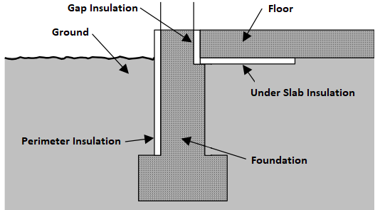
PerimeterInsulation/Layer/NominalRValuedouble
F-ft2-hr/Btu
>= 0
Yes
R-value of vertical insulation (see figure below)
PerimeterInsulation/Layer/InsulationDepthdouble
ft
>= 0
Yes
Depth from top of slab to bottom of vertical insulation
UnderSlabInsulation/SystemIdentifierid
Yes
Unique identifier
UnderSlabInsulation/Layer/NominalRValuedouble
F-ft2-hr/Btu
>= 0
Yes
R-value of horizontal insulation (see figure below)
UnderSlabInsulation/Layer/InsulationWidthdouble
ft
>= 0
See [88]
Width from slab edge inward of horizontal insulation
UnderSlabInsulation/Layer/InsulationSpansEntireSlabboolean
See [89]
Whether horizontal insulation spans entire slab
extension/GapInsulationRValuedouble
F-ft2-hr/Btu
>= 0
No
See [90]
R-value of gap insulation (see figure below)
extension/CarpetFractiondouble
frac
>= 0, <= 1
Yes
Fraction of slab covered by carpet
extension/CarpetRValuedouble
F-ft2-hr/Btu
>= 0
Yes
Carpet R-value
An example of calculating slab exposed perimeter is shown below:
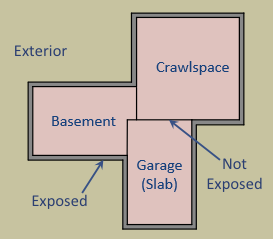
As illustrated above, basement slab edge adjacent to a garage slab or crawlspace is not considered exposed perimeter. It is quite uncommon for a slab to have an exposed perimeter of zero. Heat transfer is only calculated for the length of exposed perimeter; the rest of the perimeter is assumed to have minimal heat transfer.
Slab insulation locations can be visualized in the figure below:
HPXML Windows
Each window or glass door area is entered as a /HPXML/Building/BuildingDetails/Enclosure/Windows/Window.
Element
Type
Units
Constraints
Required
Default
Notes
SystemIdentifierid
Yes
Unique identifier
Areadouble
ft2
> 0
Yes
Total area [91]
Azimuthinteger
deg
>= 0, <= 359
Yes
Azimuth (clockwise from North)
UFactordouble
Btu/F-ft2-hr
> 0
Yes
Full-assembly NFRC U-factor
SHGCdouble
> 0, < 1
Yes
Full-assembly NFRC solar heat gain coefficient
Overhangselement
No
<none>
Presence of overhangs (including roof eaves)
FractionOperabledouble
frac
>= 0, <= 1
Yes
Operable fraction [92]
PerformanceClassstring
See [93]
No
residential
Performance class
AttachedToWallidref
See [94]
Yes
ID of attached wall
If overhangs are specified, additional information is entered in Overhangs.
HPXML Skylights
Each skylight is entered as a /HPXML/Building/BuildingDetails/Enclosure/Skylights/Skylight.
Element
Type
Units
Constraints
Required
Default
Notes
SystemIdentifierid
Yes
Unique identifier
Areadouble
ft2
> 0
Yes
Total area [97]
Azimuthinteger
deg
>= 0, <= 359
Yes
Azimuth (clockwise from North)
UFactordouble
Btu/F-ft2-hr
> 0
Yes
Full-assembly NFRC U-factor
SHGCdouble
> 0, < 1
Yes
Full-assembly NFRC solar heat gain coefficient
AttachedToRoofidref
See [98]
Yes
ID of attached roof
AttachedToFlooridref
See [99]
See [100]
ID of attached attic floor for a skylight with a shaft or sun tunnel
extension/Curbelement
No
<none>
Presence of curb (skylight wall above the roof deck) [101]
extension/Shaftelement
No
<none>
Presence of shaft (skylight wall below the roof deck) [102]
Skylight Curb
If the skylight has a curb, additional information is entered in Skylight.
Element
Type
Units
Constraints
Required
Default
Notes
extension/Curb/Areadouble
ft2
> 0
Yes
Total area including all sides
extension/Curb/AssemblyEffectiveRValuedouble
F-ft2-hr/Btu
> 0
Yes
Assembly R-value [103]
Skylight Shaft
If the skylight has a shaft, additional information is entered in Skylight.
Element
Type
Units
Constraints
Required
Default
Notes
extension/Shaft/Areadouble
ft2
> 0
Yes
Total area including all sides
extension/Shaft/AssemblyEffectiveRValuedouble
F-ft2-hr/Btu
> 0
Yes
Assembly R-value [104]
HPXML Doors
Each door with opaque area is entered as a /HPXML/Building/BuildingDetails/Enclosure/Doors/Door.
Element
Type
Units
Constraints
Required
Default
Notes
SystemIdentifierid
Yes
Unique identifier
AttachedToWallidref
See [105]
Yes
ID of attached wall
Areadouble
ft2
> 0
Yes
Total opaque area [106]
Azimuthinteger
deg
>= 0, <= 359
Yes
Azimuth (clockwise from North)
RValuedouble
F-ft2-hr/Btu
> 0
Yes
R-value [107]
HPXML Systems
The dwelling unit’s systems are entered in /HPXML/Building/BuildingDetails/Systems.
HPXML Heating Systems
The following heating system types can be modeled:
Electric Resistance
Each electric resistance heating system is entered as a /HPXML/Building/BuildingDetails/Systems/HVAC/HVACPlant/HeatingSystem.
Element
Type
Units
Constraints
Required
Default
Notes
SystemIdentifierid
Yes
Unique identifier
HeatingSystemType/ElectricResistanceelement
Yes
Type of heating system
HeatingSystemFuelstring
electricity
Yes
Fuel type
HeatingCapacitydouble
Btu/hr
>= 0 [108]
Yes
Heating output capacity
AnnualHeatingEfficiency[Units="Percent"]/Valuedouble
frac
> 0, <= 1
Yes
Heating efficiency
FractionHeatLoadServeddouble
frac
>= 0, <= 1 [109]
Yes
Fraction of heating load served
Furnace
Each central furnace is entered as a /HPXML/Building/BuildingDetails/Systems/HVAC/HVACPlant/HeatingSystem.
Element
Type
Units
Constraints
Required
Default
Notes
SystemIdentifierid
Yes
Unique identifier
DistributionSystemidref
See [110]
Yes
ID of attached distribution system
HeatingSystemType/Furnaceelement
Yes
Type of heating system
HeatingSystemFuelstring
See [111]
Yes
Fuel type
HeatingCapacitydouble
Btu/hr
>= 0 [112]
Yes
Heating output capacity
AnnualHeatingEfficiency[Units="AFUE"]/Valuedouble
frac
> 0, <= 1
Yes
Rated heating efficiency
FractionHeatLoadServeddouble
frac
>= 0, <= 1 [113]
Yes
Fraction of heating load served
extension/FanMotorTypestring
See [114]
No
See [115]
Blower fan model type
extension/FanPowerWattsPerCFMdouble
W/cfm
>= 0 [116]
Yes
Blower fan efficiency at maximum fan speed [117]
extension/HeatingDesignAirflowCFMdouble
cfm
>= 0
No
240 cfm/ton
Blower fan heating design airflow rate [118]
extension/AirflowDefectRatiodouble
frac
>= -0.9, <= 9
Yes
Deviation between design/installed airflow rates [119]
Warning
HVAC installation grading inputs (i.e., FanPowerWattsPerCFM and AirflowDefectRatio) should be provided per the conditions specified in ANSI/RESNET/ACCA 310-2020.
OS-ERI does not check that, for example, the total duct leakage requirement has been met or that a Grade I/II input is appropriate per the ANSI 310 process flow; that is currently the responsibility of the software developer.
Wall Furnace
Each wall furnace is entered as a /HPXML/Building/BuildingDetails/Systems/HVAC/HVACPlant/HeatingSystem.
Element
Type
Units
Constraints
Required
Default
Notes
SystemIdentifierid
Yes
Unique identifier
HeatingSystemType/WallFurnaceelement
Yes
Type of heating system
HeatingSystemFuelstring
See [120]
Yes
Fuel type
HeatingCapacitydouble
Btu/hr
>= 0 [121]
Yes
Heating output capacity
AnnualHeatingEfficiency[Units="AFUE"]/Valuedouble
frac
> 0, <= 1
Yes
Rated heating efficiency
FractionHeatLoadServeddouble
frac
>= 0, <= 1 [122]
Yes
Fraction of heating load served
extension/FanPowerWattsdouble
W
>= 0
No
0
Fan power
Floor Furnace
Each floor furnace is entered as a /HPXML/Building/BuildingDetails/Systems/HVAC/HVACPlant/HeatingSystem.
Element
Type
Units
Constraints
Required
Default
Notes
SystemIdentifierid
Yes
Unique identifier
HeatingSystemType/FloorFurnaceelement
Yes
Type of heating system
HeatingSystemFuelstring
See [123]
Yes
Fuel type
HeatingCapacitydouble
Btu/hr
>= 0 [124]
Yes
Heating output capacity
AnnualHeatingEfficiency[Units="AFUE"]/Valuedouble
frac
> 0, <= 1
Yes
Rated heating efficiency
FractionHeatLoadServeddouble
frac
>= 0, <= 1 [125]
Yes
Fraction of heating load served
extension/FanPowerWattsdouble
W
>= 0
No
0
Fan power
Boiler (In-Unit)
Each in-unit boiler is entered as a /HPXML/Building/BuildingDetails/Systems/HVAC/HVACPlant/HeatingSystem.
Element
Type
Units
Constraints
Required
Default
Notes
SystemIdentifierid
Yes
Unique identifier
DistributionSystemidref
See [126]
Yes
ID of attached distribution system
HeatingSystemType/Boilerelement
Yes
Type of heating system
HeatingSystemFuelstring
See [127]
Yes
Fuel type
HeatingCapacitydouble
Btu/hr
>= 0 [128]
Yes
Heating output capacity
AnnualHeatingEfficiency[Units="AFUE"]/Valuedouble
frac
> 0, <= 1
Yes
Rated heating efficiency
FractionHeatLoadServeddouble
frac
>= 0, <= 1 [129]
Yes
Fraction of heating load served
Stove
Each stove is entered as a /HPXML/Building/BuildingDetails/Systems/HVAC/HVACPlant/HeatingSystem.
Element
Type
Units
Constraints
Required
Default
Notes
SystemIdentifierid
Yes
Unique identifier
HeatingSystemType/Stoveelement
Yes
Type of heating system
HeatingSystemFuelstring
See [134]
Yes
Fuel type
HeatingCapacitydouble
Btu/hr
>= 0 [135]
Yes
Heating output capacity
AnnualHeatingEfficiency[Units="Percent"]/Valuedouble
frac
> 0, <= 1
Yes
Heating efficiency
FractionHeatLoadServeddouble
frac
>= 0, <= 1 [136]
Yes
Fraction of heating load served
extension/FanPowerWattsdouble
W
>= 0
No
40
Fan power
Space Heater
Each space heater is entered as a /HPXML/Building/BuildingDetails/Systems/HVAC/HVACPlant/HeatingSystem.
Element
Type
Units
Constraints
Required
Default
Notes
SystemIdentifierid
Yes
Unique identifier
HeatingSystemType/SpaceHeaterelement
Yes
Type of heating system
HeatingSystemFuelstring
See [137]
Yes
Fuel type
HeatingCapacitydouble
Btu/hr
>= 0 [138]
Yes
Heating output capacity
AnnualHeatingEfficiency[Units="Percent"]/Valuedouble
frac
> 0, <= 1
Yes
Heating efficiency
FractionHeatLoadServeddouble
frac
>= 0, <= 1 [139]
Yes
Fraction of heating load served
extension/FanPowerWattsdouble
W
>= 0
No
0
Fan power
Fireplace
Each fireplace is entered as a /HPXML/Building/BuildingDetails/Systems/HVAC/HVACPlant/HeatingSystem.
Element
Type
Units
Constraints
Required
Default
Notes
SystemIdentifierid
Yes
Unique identifier
HeatingSystemType/Fireplaceelement
Yes
Type of heating system
HeatingSystemFuelstring
See [140]
Yes
Fuel type
HeatingCapacitydouble
Btu/hr
>= 0 [141]
Yes
Heating output capacity
AnnualHeatingEfficiency[Units="Percent"]/Valuedouble
frac
> 0, <= 1
Yes
Heating efficiency
FractionHeatLoadServeddouble
frac
>= 0, <= 1 [142]
Yes
Fraction of heating load served
extension/FanPowerWattsdouble
W
>= 0
No
0
Fan power
HPXML Cooling Systems
The following cooling system types can be modeled:
Central Air Conditioner
Each central air conditioner is entered as a /HPXML/Building/BuildingDetails/Systems/HVAC/HVACPlant/CoolingSystem.
Element
Type
Units
Constraints
Required
Default
Notes
SystemIdentifierid
Yes
Unique identifier
DistributionSystemidref
See [143]
Yes
ID of attached distribution system
CoolingSystemTypestring
central air conditioner
Yes
Type of cooling system
CoolingSystemFuelstring
electricity
Yes
Fuel type
CoolingCapacitydouble
Btu/hr
>= 0 [144]
Yes
Cooling output capacity
CompressorTypestring
See [145]
Yes
Type of compressor
FractionCoolLoadServeddouble
frac
>= 0, <= 1 [146]
Yes
Fraction of cooling load served
AnnualCoolingEfficiency[Units="SEER2" or Units="SEER"]/Valuedouble
Btu/Wh
> 0
Yes
Rated cooling efficiency [147]
AnnualCoolingEfficiency[Units="EER2" or Units="EER"]/Valuedouble
Btu/Wh
> 0 [148]
Yes
Rated cooling efficiency [149]
extension/FanMotorTypestring
See [150]
No
See [151]
Blower fan model type
extension/FanPowerWattsPerCFMdouble
W/cfm
>= 0 [152]
Yes
Blower fan efficiency at maximum fan speed [153]
extension/CoolingDesignAirflowCFMdouble
cfm
>= 0
No
360 cfm/ton
Blower fan cooling design airflow rate [154]
extension/AirflowDefectRatiodouble
frac
>= -0.9, <= 9
Yes
Deviation between design/installed airflow rates [155]
extension/ChargeDefectRatiodouble
frac
-0.25, 0, 0.25
Yes
Deviation between design/installed refrigerant charges [156]
extension/EquipmentTypestring
See [157]
No
split system
Equipment type only used for SEER/SEER2 and EER/EER2 conversions
Warning
HVAC installation grading inputs (i.e., FanPowerWattsPerCFM, AirflowDefectRatio, and ChargeDefectRatio) should be provided per the conditions specified in ANSI/RESNET/ACCA 310-2020.
OS-ERI does not check that, for example, the total duct leakage requirement has been met or that a Grade I/II input is appropriate per the ANSI 310 process flow; that is currently the responsibility of the software developer.
Room Air Conditioner
Each room air conditioner is entered as a /HPXML/Building/BuildingDetails/Systems/HVAC/HVACPlant/CoolingSystem.
Element
Type
Units
Constraints
Required
Default
Notes
SystemIdentifierid
Yes
Unique identifier
CoolingSystemTypestring
room air conditioner
Yes
Type of cooling system
CoolingSystemFuelstring
electricity
Yes
Fuel type
CoolingCapacitydouble
Btu/hr
>= 0 [158]
Yes
Cooling output capacity
FractionCoolLoadServeddouble
frac
>= 0, <= 1 [159]
Yes
Fraction of cooling load served
AnnualCoolingEfficiency[Units="CEER" or Units="EER"]/Valuedouble
Btu/Wh
> 0
Yes
Rated cooling efficiency
IntegratedHeatingSystemFuelstring
See [160]
No
<none>
Fuel type of integrated heater
If the room air conditioner has integrated heating, additional information is entered in CoolingSystem.
Note that a room air conditioner with reverse cycle heating should be entered as a heat pump; see Room Air Conditioner w/ Reverse Cycle.
Element
Type
Units
Constraints
Required
Default
Notes
IntegratedHeatingSystemCapacitydouble
Btu/hr
>= 0 [161]
Yes
Heating output capacity of integrated heater
IntegratedHeatingSystemAnnualEfficiency[Units="Percent"]/Valuedouble
frac
> 0, <= 1
Yes
Efficiency of integrated heater
IntegratedHeatingSystemFractionHeatLoadServeddouble
frac
>= 0, <= 1 [162]
Yes
Fraction of heating load served
Packaged Terminal Air Conditioner
Each packaged terminal air conditioner (PTAC) is entered as a /HPXML/Building/BuildingDetails/Systems/HVAC/HVACPlant/CoolingSystem.
Element
Type
Units
Constraints
Required
Default
Notes
SystemIdentifierid
Yes
Unique identifier
CoolingSystemTypestring
packaged terminal air conditioner
Yes
Type of cooling system
CoolingSystemFuelstring
electricity
Yes
Fuel type
CoolingCapacitydouble
Btu/hr
>= 0 [163]
Yes
Cooling output capacity
FractionCoolLoadServeddouble
frac
>= 0, <= 1 [164]
Yes
Fraction of cooling load served
AnnualCoolingEfficiency[Units="CEER" or Units="EER"]/Valuedouble
Btu/Wh
> 0
Yes
Rated cooling efficiency
IntegratedHeatingSystemFuelstring
See [165]
No
<none>
Fuel type of integrated heater
If the PTAC has integrated heating, additional information is entered in CoolingSystem.
Note that a packaged terminal heat pump should be entered as a heat pump; see Packaged Terminal Heat Pump.
Element
Type
Units
Constraints
Required
Default
Notes
IntegratedHeatingSystemCapacitydouble
Btu/hr
>= 0 [166]
Yes
Heating output capacity of integrated heater
IntegratedHeatingSystemAnnualEfficiency[Units="Percent"]/Valuedouble
frac
> 0, <= 1
Yes
Efficiency of integrated heater
IntegratedHeatingSystemFractionHeatLoadServeddouble
frac
>= 0, <= 1 [167]
Yes
Fraction of heating load served
Evaporative Cooler
Each evaporative cooler is entered as a /HPXML/Building/BuildingDetails/Systems/HVAC/HVACPlant/CoolingSystem.
Element
Type
Units
Constraints
Required
Default
Notes
SystemIdentifierid
Yes
Unique identifier
DistributionSystemidref
See [168]
No
ID of attached distribution system
CoolingSystemTypestring
evaporative cooler
Yes
Type of cooling system
CoolingSystemFuelstring
electricity
Yes
Fuel type
CoolingCapacitydouble
Btu/hr
>= 0 [169]
Yes
Cooling output capacity
FractionCoolLoadServeddouble
frac
>= 0, <= 1 [170]
Yes
Fraction of cooling load served
Mini-Split Air Conditioner
Each mini-split air conditioner is entered as a /HPXML/Building/BuildingDetails/Systems/HVAC/HVACPlant/CoolingSystem.
Element
Type
Units
Constraints
Required
Default
Notes
SystemIdentifierid
Yes
Unique identifier
DistributionSystemidref
See [171]
No
ID of attached distribution system
CoolingSystemTypestring
mini-split
Yes
Type of cooling system
CoolingSystemFuelstring
electricity
Yes
Fuel type
CoolingCapacitydouble
Btu/hr
>= 0 [172]
Yes
Cooling output capacity
CompressorTypestring
variable speed
Yes
Type of compressor
FractionCoolLoadServeddouble
frac
>= 0, <= 1 [173]
Yes
Fraction of cooling load served
AnnualCoolingEfficiency[Units="SEER2" or Units="SEER"]/Valuedouble
Btu/Wh
> 0
Yes
Rated cooling efficiency [174]
AnnualCoolingEfficiency[Units="EER2" or Units="EER"]/Valuedouble
Btu/Wh
> 0 [175]
Yes
Rated cooling efficiency [176]
extension/FanMotorTypestring
See [177]
No
BPM
Blower fan model type
extension/FanPowerWattsPerCFMdouble
W/cfm
>= 0 [178]
Yes
Blower fan efficiency at maximum fan speed [179]
extension/CoolingDesignAirflowCFMdouble
cfm
>= 0
No
360 cfm/ton
Blower fan cooling design airflow rate [180]
extension/AirflowDefectRatiodouble
frac
>= -0.9, <= 9
Yes
Deviation between design/installed airflow rates [181]
extension/ChargeDefectRatiodouble
frac
-0.25, 0, 0.25
Yes
Deviation between design/installed refrigerant charges [182]
Warning
HVAC installation grading inputs (i.e., FanPowerWattsPerCFM, AirflowDefectRatio, and ChargeDefectRatio) should be provided per the conditions specified in ANSI/RESNET/ACCA 310-2020.
OS-ERI does not check that, for example, the total duct leakage requirement has been met or that a Grade I/II input is appropriate per the ANSI 310 process flow; that is currently the responsibility of the software developer.
HPXML Heat Pumps
The following heat pump types can be modeled:
Air-to-Air Heat Pump
Each air-to-air heat pump is entered as a /HPXML/Building/BuildingDetails/Systems/HVAC/HVACPlant/HeatPump.
Element
Type
Units
Constraints
Required
Default
Notes
SystemIdentifierid
Yes
Unique identifier
DistributionSystemidref
See [188]
Yes
ID of attached distribution system
HeatPumpTypestring
air-to-air
Yes
Type of heat pump
HeatPumpFuelstring
electricity
Yes
Fuel type
HeatingCapacitydouble
Btu/hr
>= 0 [189]
Yes
Heating output capacity at 47F
HeatingCapacity17Fdouble
Btu/hr
>= 0, <= HeatingCapacity
Yes
Heating output capacity at 17F
CoolingCapacitydouble
Btu/hr
>= 0
Yes
Cooling output capacity
CompressorTypestring
See [190]
Yes
Type of compressor
CompressorLockoutTemperaturedouble
F
No
See [191]
Minimum outdoor temperature for compressor operation
BackupTypestring
integrated
No
<none>
Type of backup heating [192]
FractionHeatLoadServeddouble
frac
>= 0, <= 1 [193]
Yes
Fraction of heating load served
FractionCoolLoadServeddouble
frac
>= 0, <= 1 [194]
Yes
Fraction of cooling load served
AnnualCoolingEfficiency[Units="SEER2" or Units="SEER"]/Valuedouble
Btu/Wh
> 0
Yes
Rated cooling efficiency [195]
AnnualCoolingEfficiency[Units="EER2" or Units="EER"]/Valuedouble
Btu/Wh
> 0 [196]
Yes
Rated cooling efficiency [197]
AnnualHeatingEfficiency[Units="HSPF2" or Units="HSPF"]/Valuedouble
Btu/Wh
> 0
Yes
Rated heating efficiency [198]
extension/FanMotorTypestring
See [199]
No
See [200]
Blower fan model type
extension/FanPowerWattsPerCFMdouble
W/cfm
>= 0
Yes
Blower fan efficiency at maximum fan speed [201]
extension/HeatingDesignAirflowCFMdouble
cfm
>= 0
No
See [202]
Blower fan heating design airflow rate [203]
extension/CoolingDesignAirflowCFMdouble
cfm
>= 0
No
See [204]
Blower fan cooling design airflow rate [205]
extension/AirflowDefectRatiodouble
frac
>= -0.9, <= 9
Yes
Deviation between design/installed airflow rates [206]
extension/ChargeDefectRatiodouble
frac
-0.25, 0, 0.25
Yes
Deviation between design/installed refrigerant charges [207]
extension/EquipmentTypestring
See [208]
No
split system
Equipment type only used for SEER/SEER2, EER/EER2, and HSPF/HSPF2 conversions
Warning
HVAC installation grading inputs (i.e., FanPowerWattsPerCFM, AirflowDefectRatio, and ChargeDefectRatio) should be provided per the conditions specified in ANSI/RESNET/ACCA 310-2020.
OS-ERI does not check that, for example, the total duct leakage requirement has been met or that a Grade I/II input is appropriate per the ANSI 310 process flow; that is currently the responsibility of the software developer.
Mini-Split Heat Pump
Each mini-split heat pump is entered as a /HPXML/Building/BuildingDetails/Systems/HVAC/HVACPlant/HeatPump.
Each HeatPump should represent a single outdoor unit, whether connected to one indoor head or multiple indoor heads.
Element
Type
Units
Constraints
Required
Default
Notes
SystemIdentifierid
Yes
Unique identifier
DistributionSystemidref
See [209]
No
ID of attached distribution system, if present
HeatPumpTypestring
mini-split
Yes
Type of heat pump
HeatPumpFuelstring
electricity
Yes
Fuel type
HeatingCapacitydouble
Btu/hr
>= 0 [210]
Yes
Heating output capacity at 47F
HeatingCapacity17Fdouble
Btu/hr
>= 0, <= HeatingCapacity
Yes
Heating output capacity at 17F
CoolingCapacitydouble
Btu/hr
>= 0
Yes
Cooling output capacity
CompressorTypestring
variable speed
Yes
Type of compressor
CompressorLockoutTemperaturedouble
F
No
See [211]
Minimum outdoor temperature for compressor operation
BackupTypestring
integrated
No
<none>
Type of backup heating [212]
FractionHeatLoadServeddouble
frac
>= 0, <= 1 [213]
Yes
Fraction of heating load served
FractionCoolLoadServeddouble
frac
>= 0, <= 1 [214]
Yes
Fraction of cooling load served
AnnualCoolingEfficiency[Units="SEER2" or Units="SEER"]/Valuedouble
Btu/Wh
> 0
Yes
Rated cooling efficiency [215]
AnnualCoolingEfficiency[Units="EER2" or Units="EER"]/Valuedouble
Btu/Wh
> 0 [216]
Yes
Rated cooling efficiency [217]
AnnualHeatingEfficiency[Units="HSPF2" or Units="HSPF"]/Valuedouble
Btu/Wh
> 0
Yes
Rated heating efficiency [218]
extension/FanMotorTypestring
See [219]
No
BPM
Blower fan model type
extension/FanPowerWattsPerCFMdouble
W/cfm
>= 0
Yes
Blower fan efficiency at maximum fan speed [220]
extension/HeatingDesignAirflowCFMdouble
cfm
>= 0
No
See [221]
Blower fan heating design airflow rate [222]
extension/CoolingDesignAirflowCFMdouble
cfm
>= 0
No
See [223]
Blower fan cooling design airflow rate [224]
extension/AirflowDefectRatiodouble
frac
>= -0.9, <= 9
Yes
Deviation between design/installed airflow rates [225]
extension/ChargeDefectRatiodouble
frac
-0.25, 0, 0.25
Yes
Deviation between design/installed refrigerant charges [226]
Warning
HVAC installation grading inputs (i.e., FanPowerWattsPerCFM, AirflowDefectRatio, and ChargeDefectRatio) should be provided per the conditions specified in ANSI/RESNET/ACCA 310-2020.
OS-ERI does not check that, for example, the total duct leakage requirement has been met or that a Grade I/II input is appropriate per the ANSI 310 process flow; that is currently the responsibility of the software developer.
Packaged Terminal Heat Pump
Each packaged terminal heat pump is entered as a /HPXML/Building/BuildingDetails/Systems/HVAC/HVACPlant/HeatPump.
Element
Type
Units
Constraints
Required
Default
Notes
SystemIdentifierid
Yes
Unique identifier
HeatPumpTypestring
packaged terminal heat pump
Yes
Type of heat pump
HeatPumpFuelstring
electricity
Yes
Fuel type
HeatingCapacitydouble
Btu/hr
>= 0 [227]
Yes
Heating output capacity at 47F
HeatingCapacity17Fdouble
Btu/hr
>= 0, <= HeatingCapacity
No
Heating output capacity at 17F
CoolingCapacitydouble
Btu/hr
>= 0
Yes
Cooling output capacity
CompressorLockoutTemperaturedouble
F
No
See [228]
Minimum outdoor temperature for compressor operation
BackupTypestring
integrated
No
<none>
Type of backup heating [229]
FractionHeatLoadServeddouble
frac
>= 0, <= 1 [230]
Yes
Fraction of heating load served
FractionCoolLoadServeddouble
frac
>= 0, <= 1 [231]
Yes
Fraction of cooling load served
AnnualCoolingEfficiency[Units="CEER" or Units="EER"]/Valuedouble
Btu/Wh
> 0
Yes
Rated cooling efficiency
AnnualHeatingEfficiency[Units="COP"]/Valuedouble
W/W
> 0
Yes
Rated heating efficiency
Room Air Conditioner w/ Reverse Cycle
Each room air conditioner with reverse cycle is entered as a /HPXML/Building/BuildingDetails/Systems/HVAC/HVACPlant/HeatPump.
Element
Type
Units
Constraints
Required
Default
Notes
SystemIdentifierid
Yes
Unique identifier
HeatPumpTypestring
room air conditioner with reverse cycle
Yes
Type of heat pump
HeatPumpFuelstring
electricity
Yes
Fuel type
HeatingCapacitydouble
Btu/hr
>= 0 [232]
Yes
Heating output capacity at 47F
HeatingCapacity17Fdouble
Btu/hr
>= 0, <= HeatingCapacity
No
Heating output capacity at 17F
CoolingCapacitydouble
Btu/hr
>= 0
Yes
Cooling output capacity
CompressorLockoutTemperaturedouble
F
No
See [233]
Minimum outdoor temperature for compressor operation
BackupTypestring
integrated
No
<none>
Type of backup heating [234]
FractionHeatLoadServeddouble
frac
>= 0, <= 1 [235]
Yes
Fraction of heating load served
FractionCoolLoadServeddouble
frac
>= 0, <= 1 [236]
Yes
Fraction of cooling load served
AnnualCoolingEfficiency[Units="CEER" or Units="EER"]/Valuedouble
Btu/Wh
> 0
Yes
Rated cooling efficiency
AnnualHeatingEfficiency[Units="COP"]/Valuedouble
W/W
> 0
Yes
Rated heating efficiency
Ground-to-Air Heat Pump
Each ground-to-air heat pump is entered as a /HPXML/Building/BuildingDetails/Systems/HVAC/HVACPlant/HeatPump.
Element
Type
Units
Constraints
Required
Default
Notes
SystemIdentifierid
Yes
Unique identifier
IsSharedSystemboolean
Yes
Whether it has a shared hydronic circulation loop [237]
HeatPumpTypestring
ground-to-air
Yes
Type of heat pump
HeatPumpFuelstring
electricity
Yes
Fuel type
DistributionSystemidref
See [238]
Yes
ID of attached distribution system
HeatingCapacitydouble
Btu/hr
>= 0 [239]
Yes
Heating output capacity
CoolingCapacitydouble
Btu/hr
>= 0
Yes
Cooling output capacity
BackupTypestring
integrated
No
<none>
Type of backup heating [240]
FractionHeatLoadServeddouble
frac
>= 0, <= 1 [241]
Yes
Fraction of heating load served
FractionCoolLoadServeddouble
frac
>= 0, <= 1 [242]
Yes
Fraction of cooling load served
AnnualCoolingEfficiency[Units="EER"]/Valuedouble
Btu/Wh
> 0
Yes
Rated cooling efficiency
AnnualHeatingEfficiency[Units="COP"]/Valuedouble
W/W
> 0
Yes
Rated heating efficiency
NumberofUnitsServedinteger
> 0
See [243]
Number of dwelling units served
extension/PumpPowerWattsPerTondouble
W/ton
>= 0
Yes
Pump power [244]
extension/SharedLoopWattsdouble
W
>= 0
See [245]
Shared pump power [246]
extension/SharedLoopMotorEfficiencydouble
frac
> 0, < 1
No
0.85 [247]
Shared loop motor efficiency
extension/FanMotorTypestring
See [248]
No
See [249]
Blower fan model type
extension/FanPowerWattsPerCFMdouble
W/cfm
>= 0
Yes
Blower fan efficiency at maximum fan speed [250]
extension/HeatingDesignAirflowCFMdouble
cfm
>= 0
No
See [251]
Blower fan heating design airflow rate
extension/CoolingDesignAirflowCFMdouble
cfm
>= 0
No
See [252]
Blower fan cooling design airflow rate
extension/AirflowDefectRatiodouble
frac
>= -0.9, <= 9
Yes
Deviation between design/installed airflow rates [253]
extension/ChargeDefectRatiodouble
frac
-0.25, 0, 0.25
Yes
Deviation between design/installed refrigerant charges [254]
Warning
HVAC installation grading inputs (i.e., FanPowerWattsPerCFM, AirflowDefectRatio, and ChargeDefectRatio) should be provided per the conditions specified in ANSI/RESNET/ACCA 310-2020.
OS-ERI does not check that, for example, the total duct leakage requirement has been met or that a Grade I/II input is appropriate per the ANSI 310 process flow; that is currently the responsibility of the software developer.
Water-Loop-to-Air Heat Pump
Each water-loop-to-air heat pump is entered as a /HPXML/Building/BuildingDetails/Systems/HVAC/HVACPlant/HeatPump.
Element
Type
Units
Constraints
Required
Default
Notes
SystemIdentifierid
Yes
Unique identifier
DistributionSystemidref
See [255]
Yes
ID of attached distribution system
HeatPumpTypestring
water-loop-to-air
Yes
Type of heat pump
HeatPumpFuelstring
electricity
Yes
Fuel type
HeatingCapacitydouble
Btu/hr
> 0
See [256]
Heating output capacity
CoolingCapacitydouble
Btu/hr
> 0
See [257]
Cooling output capacity
BackupTypestring
integrated
No
<none>
Type of backup heating [258]
AnnualCoolingEfficiency[Units="EER"]/Valuedouble
Btu/Wh
> 0
See [259]
Rated cooling efficiency
AnnualHeatingEfficiency[Units="COP"]/Valuedouble
W/W
> 0
See [260]
Rated heating efficiency
Note
If a water loop heat pump is specified, there must be at least one shared heating system (i.e., Boiler (In-Unit)) and/or one shared cooling system (i.e., Chiller (Shared) or Cooling Tower (Shared)) specified with water loop distribution.
Backup
If a backup type of “integrated” is provided, additional information is entered in HeatPump.
Element
Type
Units
Constraints
Required
Default
Notes
BackupSystemFuelstring
See [261]
Yes
Integrated backup heating fuel type
BackupAnnualHeatingEfficiency[Units="Percent" or Units="AFUE"]/Valuedouble
frac
> 0, <= 1
Yes
Integrated backup heating efficiency
BackupHeatingCapacitydouble
Btu/hr
>= 0 [262]
Yes
Integrated backup heating output capacity
HPXML HVAC Control
If any HVAC systems are specified, a single thermostat is entered as a /HPXML/Building/BuildingDetails/Systems/HVAC/HVACControl.
Element
Type
Units
Constraints
Required
Default
Notes
SystemIdentifierid
Yes
Unique identifier
ControlTypestring
See [263]
Yes
Type of thermostat
HPXML HVAC Distribution
Note
There can be at most one heating system and one cooling system attached to a distribution system. See HPXML Heating Systems, HPXML Cooling Systems, and HPXML Heat Pumps for information on which distribution system type is allowed for which HVAC system. Also note that some HVAC systems (e.g., room air conditioners) are not allowed to be attached to a distribution system.
Air Distribution
Each air distribution system is entered as a /HPXML/Building/BuildingDetails/Systems/HVAC/HVACDistribution.
Element
Type
Units
Constraints
Required
Default
Notes
SystemIdentifierid
Yes
Unique identifier
DistributionSystemType/AirDistributionelement
Yes
Type of distribution system
DistributionSystemType/AirDistribution/AirDistributionTypestring
See [264]
Yes
Type of air distribution
DistributionSystemType/AirDistribution/DuctLeakageMeasurement[DuctType="supply"]element
See [265]
Supply duct leakage value
DistributionSystemType/AirDistribution/DuctLeakageMeasurement[DuctType="return"]element
See [266]
Return duct leakage value
DistributionSystemType/AirDistribution/Ductselement
No
Supply/return ducts; multiple are allowed [267]
DistributionSystemType/AirDistribution/NumberofReturnRegistersinteger
>= 0
See [268]
Number of return registers
ConditionedFloorAreaServeddouble
ft2
> 0
See [269]
Conditioned floor area served
Additional information is entered in each DuctLeakageMeasurement.
Note
ANSI/RESNET/ICC 301 allows for various duct leakage exemptions, including not testing a distribution system or measuring total duct leakage in lieu of leakage to the outside. OS-ERI does not automatically handle these exemptions. Any software tool that offers these options to their end users must incorporate the necessary logic and pass the appropriate inputs to OS-ERI (i.e., leakage to the outside or distribution system efficiency (DSE)).
Additional information is entered in each Ducts.
Element
Type
Units
Constraints
Required
Default
Notes
SystemIdentifierid
Yes
Unique identifier
DuctTypestring
See [272]
Yes
Supply or return ducts
DuctInsulationRValuedouble
F-ft2-hr/Btu
>= 0
Yes
R-value of duct insulation [273]
DuctBuriedInsulationLevelstring
See [274]
No
not buried
Duct buried insulation level [275]
DuctLocationstring
See [276]
Yes
Duct location
FractionDuctAreaand/orDuctSurfaceAreadouble
frac or ft2
0-1 or >= 0 [277]
Yes [278]
See [279]
Duct fraction/surface area in location
Hydronic Distribution
Each hydronic distribution system is entered as a /HPXML/Building/BuildingDetails/Systems/HVAC/HVACDistribution.
Element
Type
Units
Constraints
Required
Default
Notes
SystemIdentifierid
Yes
Unique identifier
DistributionSystemType/HydronicDistributionelement
Yes
Type of distribution system
DistributionSystemType/HydronicDistribution/HydronicDistributionTypestring
See [280]
Yes
Type of hydronic distribution system
Distribution System Efficiency (DSE)
Warning
A simplified DSE model is provided for flexibility, but it is strongly recommended to use one of the other detailed distribution system types for better accuracy. The DSE input is simply applied to heating/cooling energy use for every hour of the year.
Each distribution system using DSE is entered as a /HPXML/Building/BuildingDetails/Systems/HVAC/HVACDistribution.
Element
Type
Units
Constraints
Required
Default
Notes
SystemIdentifierid
Yes
Unique identifier
DistributionSystemType/Otherstring
DSE
Yes
Type of distribution system
AnnualHeatingDistributionSystemEfficiencydouble
frac
> 0, <= 1
Yes
Seasonal distribution system efficiency for heating
AnnualCoolingDistributionSystemEfficiencydouble
frac
> 0, <= 1
Yes
Seasonal distribution system efficiency for cooling
DSE values can be calculated from ASHRAE Standard 152.
HPXML Mechanical Ventilation Fans
The following mechanical ventilation fan types that provide ventilation to the whole dwelling unit can be modeled:
Exhaust Only
Each exhaust only fan is entered as a /HPXML/Building/BuildingDetails/Systems/MechanicalVentilation/VentilationFans/VentilationFan.
Element
Type
Units
Constraints
Required
Default
Notes
SystemIdentifierid
Yes
Unique identifier
FanTypestring
exhaust only
Yes
Type of ventilation system
TestedFlowRateorextension/FlowRateNotTested=truedouble or boolean
cfm
>= 0 or true
See [281]
Flow rate or whether flow rate unmeasured
HoursInOperationdouble
hrs/day
>= 0, <= 24
See [282]
Hours per day of operation
UsedForWholeBuildingVentilationboolean
true
Yes
Ventilation fan use case [283]
IsSharedSystemboolean
Yes
Whether it serves multiple dwelling units [284]
FanPowerorextension/FanPowerDefaulted=truedouble or boolean
W
>= 0 or true
Yes
Fan power or whether fan power is unknown
Supply Only
Each supply only fan is entered as a /HPXML/Building/BuildingDetails/Systems/MechanicalVentilation/VentilationFans/VentilationFan.
Element
Type
Units
Constraints
Required
Default
Notes
SystemIdentifierid
Yes
Unique identifier
FanTypestring
supply only
Yes
Type of ventilation system
TestedFlowRateorextension/FlowRateNotTested=truedouble or boolean
cfm
>= 0 or true
See [285]
Flow rate or whether flow rate unmeasured
HoursInOperationdouble
hrs/day
>= 0, <= 24
See [286]
Hours per day of operation
UsedForWholeBuildingVentilationboolean
true
Yes
Ventilation fan use case [287]
IsSharedSystemboolean
Yes
Whether it serves multiple dwelling units [288]
FanPowerorextension/FanPowerDefaulted=truedouble or boolean
W
>= 0 or true
Yes
Fan power or whether fan power is unknown
Balanced
Each balanced (supply and exhaust) fan is entered as a /HPXML/Building/BuildingDetails/Systems/MechanicalVentilation/VentilationFans/VentilationFan.
Element
Type
Units
Constraints
Required
Default
Notes
SystemIdentifierid
Yes
Unique identifier
FanTypestring
balanced
Yes
Type of ventilation system
TestedFlowRateorextension/FlowRateNotTested=truedouble or boolean
cfm
>= 0 or true
See [289]
Flow rate or whether flow rate unmeasured
HoursInOperationdouble
hrs/day
>= 0, <= 24
See [290]
Hours per day of operation
UsedForWholeBuildingVentilationboolean
true
Yes
Ventilation fan use case [291]
IsSharedSystemboolean
Yes
Whether it serves multiple dwelling units [292]
FanPowerorextension/FanPowerDefaulted=truedouble or boolean
W
>= 0 or true
Yes
Fan power or whether fan power is unknown
Heat Recovery Ventilator (HRV)
Each heat recovery ventilator (HRV) is entered as a /HPXML/Building/BuildingDetails/Systems/MechanicalVentilation/VentilationFans/VentilationFan.
Element
Type
Units
Constraints
Required
Default
Notes
SystemIdentifierid
Yes
Unique identifier
FanTypestring
heat recovery ventilator
Yes
Type of ventilation system
TestedFlowRateorextension/FlowRateNotTested=truedouble or boolean
cfm
>= 0 or true
See [293]
Flow rate or whether flow rate unmeasured
HoursInOperationdouble
hrs/day
>= 0, <= 24
See [294]
Hours per day of operation
UsedForWholeBuildingVentilationboolean
true
Yes
Ventilation fan use case [295]
IsSharedSystemboolean
Yes
Whether it serves multiple dwelling units [296]
SensibleRecoveryEfficiencyorAdjustedSensibleRecoveryEfficiencydouble
frac
> 0, <= 1
Yes
(Adjusted) Sensible recovery efficiency [297]
FanPowerorextension/FanPowerDefaulted=truedouble or boolean
W
>= 0 or true
Yes
Fan power or whether fan power is unknown
Energy Recovery Ventilator (ERV)
Each energy recovery ventilator (ERV) is entered as a /HPXML/Building/BuildingDetails/Systems/MechanicalVentilation/VentilationFans/VentilationFan.
Element
Type
Units
Constraints
Required
Default
Notes
SystemIdentifierid
Yes
Unique identifier
FanTypestring
energy recovery ventilator
Yes
Type of ventilation system
TestedFlowRateorextension/FlowRateNotTested=truedouble or boolean
cfm
>= 0 or true
See [298]
Flow rate or whether flow rate unmeasured
HoursInOperationdouble
hrs/day
>= 0, <= 24
See [299]
Hours per day of operation
UsedForWholeBuildingVentilationboolean
true
Yes
Ventilation fan use case [300]
IsSharedSystemboolean
Yes
Whether it serves multiple dwelling units [301]
TotalRecoveryEfficiencyorAdjustedTotalRecoveryEfficiencydouble
frac
> 0, <= 1
Yes
(Adjusted) Total recovery efficiency [302]
SensibleRecoveryEfficiencyorAdjustedSensibleRecoveryEfficiencydouble
frac
> 0, <= 1
Yes
(Adjusted) Sensible recovery efficiency [303]
FanPowerorextension/FanPowerDefaulted=truedouble or boolean
W
>= 0 or true
Yes
Fan power or whether fan power is unknown
Central Fan Integrated Supply (CFIS)
Each central fan integrated supply (CFIS) system is entered as a /HPXML/Building/BuildingDetails/Systems/MechanicalVentilation/VentilationFans/VentilationFan.
A CFIS system is a supply ventilation system with an outdoor air inlet duct on the return side of a forced-air HVAC system.
Element
Type
Units
Constraints
Required
Default
Notes
SystemIdentifierid
Yes
Unique identifier
FanTypestring
central fan integrated supply
Yes
Type of ventilation system
CFISControls/HasOutdoorAirControlboolean
Yes
Presence of controls to block outdoor air when not ventilating [304]
CFISControls/AdditionalRuntimeOperatingModestring
See [305]
Yes
How additional ventilation is provided (beyond when the HVAC system is running)
CFISControls/SupplementalFanidref
See [306]
See [307]
The supplemental fan providing additional ventilation
CFISControls/extension/ControlTypestring
See [308]
Yes
Primary air handler fan control strategy [309]
CFISControls/extension/SupplementalFanRunsWithAirHandlerFanboolean
No [310]
false
Whether the supplemental fan also runs with the air handler fan [311]
TestedFlowRateorextension/FlowRateNotTested=truedouble or boolean
cfm
>= 0 or true
Yes
Flow rate [312] or whether flow rate unmeasured
HoursInOperationdouble
hrs/day
>= 0, <= 24
Yes
Hours per day of operation [313]
UsedForWholeBuildingVentilationboolean
true
Yes
Ventilation fan use case [314]
AttachedToHVACDistributionSystemidref
See [315]
Yes
ID of attached distribution system
HPXML Whole House Fans
Each whole house fan that provides cooling load reduction is entered as a /HPXML/Building/BuildingDetails/Systems/MechanicalVentilation/VentilationFans/VentilationFan.
Element
Type
Units
Constraints
Required
Default
Notes
SystemIdentifierid
Yes
Unique identifier
UsedForSeasonalCoolingLoadReductionboolean
true
Yes
Ventilation fan use case [322]
RatedFlowRatedouble
cfm
>= 0
Yes
Flow rate
FanPowerdouble
W
>= 0
Yes
Fan power
Note
The whole house fan is assumed to operate during hours of favorable outdoor conditions and will take priority over operable windows (natural ventilation).
HPXML Water Heating Systems
The following water heater types can be modeled:
Conventional Storage
Each conventional storage water heater is entered as a /HPXML/Building/BuildingDetails/Systems/WaterHeating/WaterHeatingSystem.
Element
Type
Units
Constraints
Required
Default
Notes
SystemIdentifierid
Yes
Unique identifier
FuelTypestring
See [323]
Yes
Fuel type
WaterHeaterTypestring
storage water heater
Yes
Type of water heater
Locationstring
See [324]
Yes
Water heater location
IsSharedSystemboolean
Yes
Whether it serves multiple dwelling units or shared laundry room
TankVolumedouble
gal
> 0
Yes
Nominal tank volume
FractionDHWLoadServeddouble
frac
>= 0, <= 1 [325]
Yes
Fraction of hot water load served [326]
HeatingCapacitydouble
Btu/hr
> 0
No
See [327]
Heating input capacity
UniformEnergyFactororEnergyFactordouble
frac
< 1
Yes
EnergyGuide label rated efficiency
FirstHourRatingdouble
gal/hr
> 0
See [328]
EnergyGuide label first hour rating
RecoveryEfficiencydouble
frac
> 0, <= 1 [329]
No
See [330]
Recovery efficiency
WaterHeaterInsulation/Jacket/JacketRValuedouble
F-ft2-hr/Btu
>= 0
No
0
R-value of additional tank insulation wrap
UsesDesuperheaterboolean
No
false
Presence of desuperheater? [331]
extension/NumberofBedroomsServedinteger
> NumberofBedrooms
See [332]
Number of bedrooms served directly or indirectly
Tankless
Each instantaneous tankless water heater is entered as a /HPXML/Building/BuildingDetails/Systems/WaterHeating/WaterHeatingSystem.
Element
Type
Units
Constraints
Required
Default
Notes
SystemIdentifierid
Yes
Unique identifier
FuelTypestring
See [333]
Yes
Fuel type
WaterHeaterTypestring
instantaneous water heater
Yes
Type of water heater
Locationstring
See [334]
Yes
Water heater location
IsSharedSystemboolean
Yes
Whether it serves multiple dwelling units or shared laundry room
FractionDHWLoadServeddouble
frac
>= 0, <= 1 [335]
Yes
Fraction of hot water load served [336]
UniformEnergyFactororEnergyFactordouble
frac
< 1
Yes
EnergyGuide label rated efficiency
UsesDesuperheaterboolean
No
false
Presence of desuperheater? [337]
extension/NumberofBedroomsServedinteger
> NumberofBedrooms
See [338]
Number of bedrooms served directly or indirectly
Heat Pump
Each heat pump water heater is entered as a /HPXML/Building/BuildingDetails/Systems/WaterHeating/WaterHeatingSystem.
Element
Type
Units
Constraints
Required
Default
Notes
SystemIdentifierid
Yes
Unique identifier
FuelTypestring
electricity
Yes
Fuel type
WaterHeaterTypestring
heat pump water heater
Yes
Type of water heater
Locationstring
See [339]
Yes
Water heater location
IsSharedSystemboolean
Yes
Whether it serves multiple dwelling units or shared laundry room
TankVolumedouble
gal
> 0
Yes
Nominal tank volume
FractionDHWLoadServeddouble
frac
>= 0, <= 1 [340]
Yes
Fraction of hot water load served [341]
UniformEnergyFactororEnergyFactordouble
frac
>= 1.45, <= 5
Yes
EnergyGuide label rated efficiency
FirstHourRatingdouble
gal/hr
> 0
See [342]
EnergyGuide label first hour rating
WaterHeaterInsulation/Jacket/JacketRValuedouble
F-ft2-hr/Btu
>= 0
No
0
R-value of additional tank insulation wrap
UsesDesuperheaterboolean
No
false
Presence of desuperheater? [343]
extension/NumberofBedroomsServedinteger
> NumberofBedrooms
See [344]
Number of bedrooms served directly or indirectly
extension/HPWHInConfinedSpaceWithoutMitigationboolean
Yes
Whether HPWH is installed in confined space without mitigation [345]
extension/HPWHContainmentVolumedouble
ft3
>= 32
See [346]
Containment volume of the space where HPWH is installed
Combi Boiler w/ Storage
Each combination boiler w/ storage tank (sometimes referred to as an indirect water heater) is entered as a /HPXML/Building/BuildingDetails/Systems/WaterHeating/WaterHeatingSystem.
Element
Type
Units
Constraints
Required
Default
Notes
SystemIdentifierid
Yes
Unique identifier
WaterHeaterTypestring
space-heating boiler with storage tank
Yes
Type of water heater
Locationstring
See [347]
Yes
Water heater location
IsSharedSystemboolean
Yes
Whether it serves multiple dwelling units or shared laundry room
TankVolumedouble
gal
> 0
Yes
Nominal volume of the storage tank
FractionDHWLoadServeddouble
frac
>= 0, <= 1 [348]
Yes
Fraction of hot water load served [349]
WaterHeaterInsulation/Jacket/JacketRValuedouble
F-ft2-hr/Btu
>= 0
No
0
R-value of additional storage tank insulation wrap
StandbyLoss[Units="F/hr"]/Valuedouble
F/hr
> 0
No
See [350]
Storage tank standby losses
RelatedHVACSystemidref
See [351]
Yes
ID of boiler
extension/NumberofBedroomsServedinteger
> NumberofBedrooms
See [352]
Number of bedrooms served directly or indirectly
Combi Boiler w/ Tankless Coil
Each combination boiler w/ tankless coil is entered as a /HPXML/Building/BuildingDetails/Systems/WaterHeating/WaterHeatingSystem.
Element
Type
Units
Constraints
Required
Default
Notes
SystemIdentifierid
Yes
Unique identifier
WaterHeaterTypestring
space-heating boiler with tankless coil
Yes
Type of water heater
Locationstring
See [353]
Yes
Water heater location
IsSharedSystemboolean
Yes
Whether it serves multiple dwelling units or shared laundry room
FractionDHWLoadServeddouble
frac
>= 0, <= 1 [354]
Yes
Fraction of hot water load served [355]
RelatedHVACSystemidref
See [356]
Yes
ID of boiler
extension/NumberofBedroomsServedinteger
> NumberofBedrooms
See [357]
Number of bedrooms served directly or indirectly
Desuperheater
If the water heater uses a desuperheater, additional information is entered in WaterHeatingSystem.
Element
Type
Units
Constraints
Required
Default
Notes
RelatedHVACSystemidref
See [358]
Yes
ID of heat pump or air conditioner
HPXML Hot Water Distribution
A single hot water distribution system must be described:
Note
In attached/multifamily buildings, only the hot water distribution system serving the dwelling unit should be defined. The hot water distribution associated with, e.g., a shared laundry room should not be defined.
Standard
A standard hot water distribution system is entered as a /HPXML/Building/BuildingDetails/Systems/WaterHeating/HotWaterDistribution.
Element
Type
Units
Constraints
Required
Default
Notes
SystemIdentifierid
Yes
Unique identifier
SystemType/Standardelement
Yes
Type of in-unit distribution system serving the dwelling unit
SystemType/Standard/PipingLengthdouble
ft
> 0
Yes
Length of piping [359]
PipeInsulation/PipeRValuedouble
F-ft2-hr/Btu
>= 0
Yes
Pipe insulation R-value
DrainWaterHeatRecoveryelement
No
<none>
Presence of drain water heat recovery device [360]
Recirculation (In-Unit)
An in-unit recirculation hot water distribution system is entered as a /HPXML/Building/BuildingDetails/Systems/WaterHeating/HotWaterDistribution.
Element
Type
Units
Constraints
Required
Default
Notes
SystemIdentifierid
Yes
Unique identifier
SystemType/Recirculationelement
Yes
Type of in-unit distribution system serving the dwelling unit
SystemType/Recirculation/ControlTypestring
See [361]
Yes
Recirculation control type
SystemType/Recirculation/RecirculationPipingLoopLengthdouble
ft
> 0
Yes
Recirculation piping loop length [362]
SystemType/Recirculation/BranchPipingLengthdouble
ft
> 0
Yes
Branch piping length [363]
SystemType/Recirculation/PumpPowerdouble
W
>= 0
Yes
Recirculation pump power
PipeInsulation/PipeRValuedouble
F-ft2-hr/Btu
>= 0
Yes
Pipe insulation R-value
DrainWaterHeatRecoveryelement
No
<none>
Presence of drain water heat recovery device [364]
Drain Water Heat Recovery
If a drain water heat recovery (DWHR) device is specified, additional information is entered in DrainWaterHeatRecovery.
HPXML Water Fixtures
Each water fixture is entered as a /HPXML/Building/BuildingDetails/Systems/WaterHeating/WaterFixture.
HPXML Solar Thermal
A single solar hot water system can be described with either simple or detailed inputs.
It is recommended to use detailed inputs and allow EnergyPlus to calculate the solar contribution to the hot water load; the simple inputs are provided if equivalent calculations are performed in another software tool.
Simple Inputs
A simple solar hot water system is entered as a /HPXML/Building/BuildingDetails/Systems/SolarThermal/SolarThermalSystem.
Warning
The solar fraction will reduce the hot water load equally for every EnergyPlus timestep.
Detailed Inputs
A detailed solar hot water system is entered as a /HPXML/Building/BuildingDetails/Systems/SolarThermal/SolarThermalSystem.
Element
Type
Units
Constraints
Required
Default
Notes
SystemIdentifierid
Yes
Unique identifier
SystemTypestring
hot water
Yes
Type of solar thermal system
CollectorAreadouble
ft2
> 0
Yes
Area
CollectorLoopTypestring
See [376]
Yes
Loop type
CollectorTypestring
See [377]
Yes
System type
CollectorAzimuthinteger
deg
>= 0, <= 359
Yes
Azimuth (clockwise from North)
CollectorTiltdouble
deg
>= 0, <= 90
Yes
Tilt relative to horizontal
CollectorRatedOpticalEfficiencydouble
frac
> 0, < 1
Yes
Rated optical efficiency [378]
CollectorRatedThermalLossesdouble
Btu/hr-ft2-F
> 0
Yes
Rated thermal losses [379]
StorageVolumedouble
gal
> 0
Yes
Hot water storage volume
ConnectedToidref
See [380]
Yes
Connected water heater
HPXML Photovoltaics
Each solar electric photovoltaic (PV) system is entered as a /HPXML/Building/BuildingDetails/Systems/Photovoltaics/PVSystem.
Many of the inputs are adopted from the PVWatts model.
Element
Type
Units
Constraints
Required
Default
Notes
SystemIdentifierid
Yes
Unique identifier
IsSharedSystemboolean
Yes
Whether it serves multiple dwelling units
Locationstring
See [381]
Yes
Mounting location
ModuleTypestring
See [382]
Yes
Type of module
Trackingstring
See [383]
Yes
Type of tracking
ArrayAzimuthinteger
deg
>= 0, <= 359
Yes
Direction panels face (clockwise from North)
ArrayTiltdouble
deg
>= 0, <= 90
Yes
Tilt relative to horizontal
MaxPowerOutputdouble
W
>= 0
Yes
Peak power
SystemLossesFractiondouble
frac
>= 0, <= 1
Yes
System losses [384]
AttachedToInverteridref
See [385]
Yes
ID of attached inverter
extension/NumberofBedroomsServedinteger
> NumberofBedrooms
See [386]
Number of bedrooms served
Each inverter inverter is entered as a /HPXML/Building/BuildingDetails/Systems/Photovoltaics/Inverter.
Element
Type
Units
Constraints
Required
Default
Notes
SystemIdentifierid
Yes
Unique identifier
InverterEfficiencydouble
frac
> 0, <= 1
Yes
Inverter efficiency [387]
HPXML Batteries
A single battery can be entered as a /HPXML/Building/BuildingDetails/Systems/Batteries/Battery.
Element
Type
Units
Constraints
Required
Default
Notes
SystemIdentifierid
Yes
Unique identifier
IsSharedSystemboolean
Yes
Whether it serves multiple dwelling units
Locationstring
See [388]
No
See [389]
Location
BatteryTypestring
See [390]
Yes
Battery type
UsableCapacity[Units="kWh"]/Valuedouble
kWh
>= 0
Yes
Usable capacity
RatedPowerOutputdouble
W
>= 0
Yes
Power output under non-peak conditions
RoundTripEfficiencydouble
frac
> 0, <= 1
Yes
Round trip efficiency
extension/NumberofBedroomsServedinteger
> NumberofBedrooms
See [391]
Number of bedrooms served
Note
The battery will charge if PV production is greater than the building electrical load and the battery is below its maximum capacity. The battery will discharge if the building electrical load is greater than the PV production and the battery is above its minimum capacity. A battery in a home without PV is not modeled.
For ERI calculations, batteries will result in a small penalty because ERI is calculated using annual energy consumption and batteries increase annual electricity consumption (due to round trip efficiency). For CO2e Index calculations, batteries can result in a credit because CO2e Index is calculated using hourly electricity emissions factors and batteries shift when electricity consumption occurs.
HPXML Generators
Each generator that provides on-site power is entered as a /HPXML/Building/BuildingDetails/Systems/extension/Generators/Generator.
Element
Type
Units
Constraints
Required
Default
Notes
SystemIdentifierid
Yes
Unique identifier
IsSharedSystemboolean
Yes
Whether it serves multiple dwelling units
FuelTypestring
See [392]
Yes
Fuel type
AnnualConsumptionkBtudouble
kBtu/yr
> 0
Yes
Annual fuel consumed
AnnualOutputkWhdouble
kWh/yr
> 0 [393]
Yes
Annual electricity produced
NumberofBedroomsServedinteger
> NumberofBedrooms
See [394]
Number of bedrooms served
Note
Generators will be modeled as operating continuously (24/7).
HPXML Appliances
Appliances entered in /HPXML/Building/BuildingDetails/Appliances.
HPXML Clothes Washer
A single clothes washer can be entered as a /HPXML/Building/BuildingDetails/Appliances/ClothesWasher.
Element
Type
Units
Constraints
Required
Default
Notes
SystemIdentifierid
Yes
Unique identifier
IsSharedApplianceboolean
Yes
Whether it serves multiple dwelling units [395]
Locationstring
See [396]
Yes
Location
IntegratedModifiedEnergyFactororModifiedEnergyFactordouble
ft3/kWh/cyc
> 0
Yes
Efficiency [397]
RatedAnnualkWhdouble
kWh/yr
> 0
Yes
EnergyGuide label annual consumption
LabelElectricRatedouble
$/kWh
> 0
Yes
EnergyGuide label electricity rate
LabelGasRatedouble
$/therm
> 0
Yes
EnergyGuide label natural gas rate
LabelAnnualGasCostdouble
$
> 0
Yes
EnergyGuide label annual gas cost
LabelUsagedouble
cyc/wk
> 0
Yes
EnergyGuide label number of cycles (not used if 301 version < 2019A)
Capacitydouble
ft3
> 0
Yes
Clothes washer volume
If the clothes washer is shared, additional information is entered in /HPXML/Building/BuildingDetails/Appliances/ClothesWasher.
Element
Type
Units
Constraints
Required
Default
Notes
AttachedToWaterHeatingSystemorAttachedToHotWaterDistributionidref
See [398]
Yes
ID of attached water heater or distribution system
Countinteger
Yes
Number of clothes washers in the shared laundry room
NumberofUnitsServedinteger
Yes
Number of dwelling units served by the shared laundry room
Note
If no clothes washer is located within the Rated Home, a clothes washer in the nearest shared laundry room on the project site shall be used if available for daily use by the occupants of the Rated Home. If there are multiple clothes washers, the clothes washer with the highest Label Energy Rating (kWh/yr) shall be used.
HPXML Clothes Dryer
A single clothes dryer can be entered as a /HPXML/Building/BuildingDetails/Appliances/ClothesDryer.
Element
Type
Units
Constraints
Required
Default
Notes
SystemIdentifierid
Yes
Unique identifier
IsSharedApplianceboolean
Yes
Whether it serves multiple dwelling units [399]
Locationstring
See [400]
Yes
Location
FuelTypestring
See [401]
Yes
Fuel type
CombinedEnergyFactororEnergyFactordouble
lb/kWh
> 0
Yes
EnergyGuide label efficiency [402]
ControlTypestring
See [403]
See [404]
Type of controls
Ventedboolean
Yes
Whether dryer is vented
If the clothes dryer is shared, additional information is entered in /HPXML/Building/BuildingDetails/Appliances/ClothesDryer.
Element
Type
Units
Constraints
Required
Default
Notes
Countinteger
Yes
Number of clothes dryers in the shared laundry room
NumberofUnitsServedinteger
Yes
Number of dwelling units served by the shared laundry room
Note
If no clothes dryer is located within the Rated Home, a clothes dryer in the nearest shared laundry room on the project site shall be used if available for daily use by the occupants of the Rated Home. If there are multiple clothes dryers, the clothes dryer with the lowest Energy Factor or Combined Energy Factor shall be used.
HPXML Dishwasher
A single dishwasher can be entered as a /HPXML/Building/BuildingDetails/Appliances/Dishwasher.
Element
Type
Units
Constraints
Required
Default
Notes
SystemIdentifierid
Yes
Unique identifier
IsSharedApplianceboolean
Yes
Whether it serves multiple dwelling units [405]
Locationstring
See [406]
Yes
Location
RatedAnnualkWhorEnergyFactordouble
kWh/yr or #
> 0
Yes
EnergyGuide label consumption/efficiency [407]
PlaceSettingCapacityinteger
#
> 0
Yes
Number of place settings
LabelElectricRatedouble
$/kWh
> 0
Yes
EnergyGuide label electricity rate (not used if 301 version < 2019A)
LabelGasRatedouble
$/therm
> 0
Yes
EnergyGuide label natural gas rate (not used if 301 version < 2019A)
LabelAnnualGasCostdouble
$
> 0
Yes
EnergyGuide label annual gas cost (not used if 301 version < 2019A)
LabelUsagedouble
cyc/wk
> 0
Yes
EnergyGuide label number of cycles (not used if 301 version < 2019A)
If the dishwasher is shared, additional information is entered in /HPXML/Building/BuildingDetails/Appliances/Dishwasher.
Element
Type
Units
Constraints
Required
Default
Notes
AttachedToWaterHeatingSystemorAttachedToHotWaterDistributionidref
See [408]
Yes
ID of attached water heater or distribution system
Note
If no dishwasher is located within the Rated Home, a dishwasher in the nearest shared kitchen in the building shall be used only if available for daily use by the occupants of the Rated Home. If there are multiple dishwashers, the dishwasher with the lowest Energy Factor (highest kWh/yr) shall be used.
HPXML Refrigerators
A single refrigerator can be entered as a /HPXML/Building/BuildingDetails/Appliances/Refrigerator.
Element
Type
Units
Constraints
Required
Default
Notes
SystemIdentifierid
Yes
Unique identifier
Locationstring
See [409]
Yes
Location
RatedAnnualkWhdouble
kWh/yr
> 0
Yes
Annual consumption
Note
If there are multiple refrigerators, the total energy consumption of all refrigerators/freezers shall be used along with the location that represents the majority of power consumption.
HPXML Dehumidifier
Each dehumidifier can be entered as a /HPXML/Building/BuildingDetails/Appliances/Dehumidifier.
Element
Type
Units
Constraints
Required
Default
Notes
SystemIdentifierid
Yes
Unique identifier
Typestring
See [410]
Yes
Type of dehumidifier
Locationstring
See [411]
Yes
Location of dehumidifier
Capacitydouble
pints/day
> 0
Yes
Dehumidification capacity
IntegratedEnergyFactororEnergyFactordouble
liters/kWh
> 0
Yes
Rated efficiency
FractionDehumidificationLoadServeddouble
frac
>= 0, <= [412]
Yes
Fraction of dehumidification load served
Note
Dehumidifiers only affect ERI scores if Version 2019AB or newer is used, as dehumidifiers were incorporated into the ERI calculation as of 301-2019 Addendum B.
Note
Dehumidifiers are currently modeled as located within conditioned space; the model is not suited for a dehumidifier in, e.g., a wet unconditioned basement or crawlspace. Therefore the dehumidifier Location is currently restricted to “conditioned space”.
HPXML Cooking Range/Oven
A single cooking range can be entered as a /HPXML/Building/BuildingDetails/Appliances/CookingRange.
If a cooking range is specified, a single oven is also entered as a /HPXML/Building/BuildingDetails/Appliances/Oven.
Element
Type
Units
Constraints
Required
Default
Notes
SystemIdentifierid
Yes
Unique identifier
IsConvectionboolean
Yes
Convection oven?
HPXML Lighting & Ceiling Fans
Lighting and ceiling fans are entered in /HPXML/Building/BuildingDetails/Lighting.
HPXML Lighting
Multiple /HPXML/Building/BuildingDetails/Lighting/LightingGroup elements must be provided, each of which is the combination of:
LightingType: ‘LightEmittingDiode’, ‘CompactFluorescent’, and ‘FluorescentTube’Location: ‘interior’, ‘exterior’, and ‘garage’ (garage lighting groups only required if a garage is present)
Use LightEmittingDiode for Tier II qualifying light fixtures; use CompactFluorescent and/or FluorescentTube for Tier I qualifying light fixtures.
Information is entered in each LightingGroup.
Element
Type
Units
Constraints
Required
Default
Notes
SystemIdentifierid
Yes
Unique identifier
LightingTypeelement
See [415]
Yes
Lighting type
Locationstring
See [416]
Yes
Lighting location [417]
FractionofUnitsInLocationdouble
frac
>= 0, <= 1 [418]
Yes
Fraction of light fixtures in the location with the specified lighting type
HPXML Ceiling Fans
Each ceiling fan is entered as a /HPXML/Building/BuildingDetails/Lighting/CeilingFan.
Element
Type
Units
Constraints
Required
Default
Notes
SystemIdentifierid
Yes
Unique identifier
Airflow[FanSpeed="medium"]/Efficiencyand/orLabelEnergyUsedouble
cfm/W or W
> 0
Yes
Efficiency at medium speed or EnergyGuide label average energy use
Countinteger
> 0
Yes
Number of similar ceiling fans
HPXML Locations
The various locations used in an HPXML file are defined as follows:
Value
Description
Temperature
Building Type
outside
Ambient environment
Weather data
Any
ground
EnergyPlus foundation model calculation
Any
conditioned space
Above-grade conditioned floor area
EnergyPlus thermal zone calculation
Any
attic - vented
EnergyPlus thermal zone calculation
Any
attic - unvented
EnergyPlus thermal zone calculation
Any
basement - conditioned
Below-grade conditioned floor area
EnergyPlus thermal zone calculation
Any
basement - unconditioned
EnergyPlus thermal zone calculation
Any
crawlspace - vented
EnergyPlus thermal zone calculation
Any
crawlspace - unvented
Use for a “conditioned” crawlspace too [419]
EnergyPlus thermal zone calculation
Any
garage
Unconditioned garage (not shared parking) [420]
EnergyPlus thermal zone calculation
Any
other housing unit
Unrated Conditioned Space
Same as conditioned space
SFA/MF only
other heated space
Unrated Heated Space
Avg of conditioned space/outside; min of 68F
SFA/MF only
other multifamily buffer space
Multifamily Buffer Boundary
Avg of conditioned space/outside; min of 50F
SFA/MF only
other non-freezing space
Non-Freezing Space
Floats with outside; minimum of 40F
SFA/MF only
other exterior
Water heater outside
Weather data
Any
exterior wall
Ducts in exterior wall
Avg of conditioned space/outside
Any
under slab
Ducts under slab (ground)
EnergyPlus foundation model calculation
Any
roof deck
Ducts on roof deck (outside)
Weather data
Any
Validating & Debugging Errors
When running HPXML files, errors may occur because:
An HPXML file provided is invalid (either relative to the HPXML schema or the ERI Use Case).
An unexpected error occurred in the workflow (e.g., applying the ERI 301 ruleset).
An unexpected EnergyPlus simulation error occurred.
If, for example, the Rated Home is unsuccessful, first look in the ERIRatedHome/run.log for details. If there are no errors in that log file, then the error may be in the EnergyPlus simulation – see ERIRatedHome/eplusout.err.
Contact us if you can’t figure out the cause of an error.
Sample Files
Dozens of sample HPXML files are included in the workflow/sample_files directory. The sample files help to illustrate how different building components are described in HPXML.
Each sample file generally makes one isolated change relative to the base HPXML (base.xml) building.
For example, the base-dhw-dwhr.xml file adds a DrainWaterHeatRecovery element to the building.
You may find it useful to search through the files for certain HPXML elements or compare (diff) a sample file to the base.xml file.